
 As I have mentioned in other posts, I am pretty active in the chat room that is associated to The Wood Whisperer. We will on occasion have challenge and trade projects, where we build something that is designed to push our skills, and then send it to another member. This time we chose to do a woodworking hand tool. Something we did a little different with this one, is we ran it similar to a secret Santa, where we found out who we would be sending our tool to before we got started. However, we did not know who we would be receiving from.
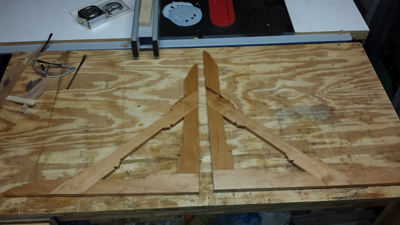
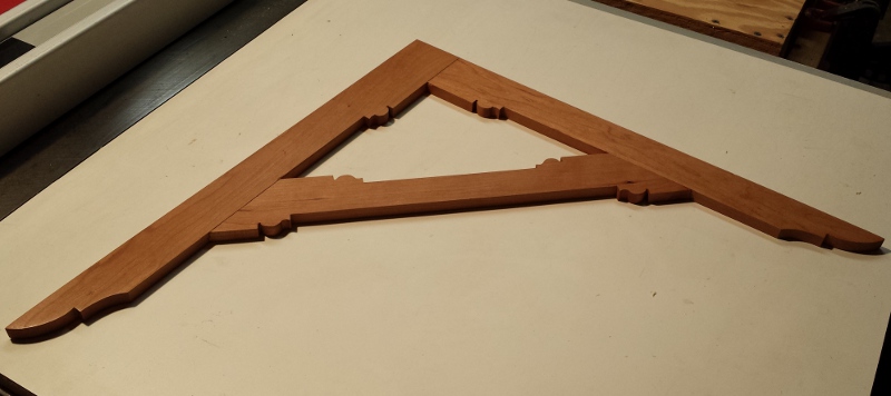
For my tool, I built an English Layout Square. Actually, I built two of them. Since I knew this project would really stretch my skills, I wanted one to practice each step, before doing the step on the piece I sent out. While the practice square has a couple obvious mistakes, it turned out well. As soon as I find a spot for it, the practice square will be hung on the wall, ready for use.
The wood I used is cherry. After milling the cherry down to 1/2″ thickness, I sized up the two main arms of the square. The joint to bring the two arms together is a bridal joint. The tenon for this bridal joint was thin, coming in about 1/8″. I made this tenon using a shop made tenon jig on the table saw. Using the same jig, I adjust the distance of the tenon jig from the blade to get the work piece as centered as possible, to allow the table saw to hog out the center.
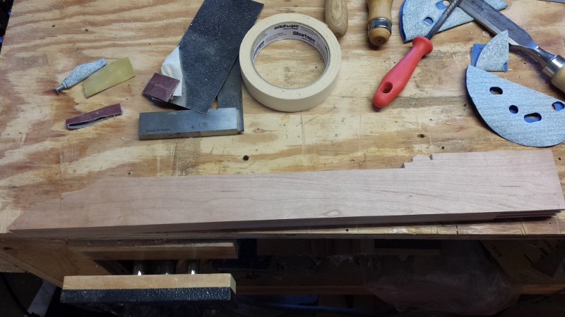 After getting the bridal joint done, the traditional English Layout Square has a lot of ornamental detail to it. I roughed out most of this detail on the band saw, and then where I could, used the oscillating spindle sander to clean up the detail. The rest, I cleaned up by hand, using my rasp, chisels, and sand paper.
Once I got the detail work done, it was time for the first glue-up. After several dry fits, I was able to get the bridal joint to fit together well. The mistake I made was I let it be a little too tight. The problem with that is the wood swelled a bit when I applied the glue. I was able to get the pieces together, but it proved to be a challenge. The other challenge to this glue-up is making sure I got the square as close to 90 degrees as possible.
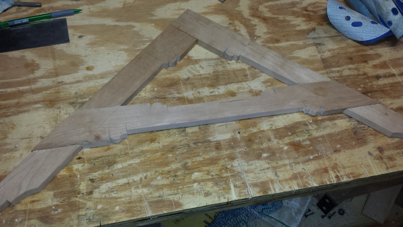 The next step was working on the cross brace. The joinery for that is two half lap joints. I did this almost entirely with hand tools. Once I establish the position of the cross brace, I stuck a line using a marking knife on the arms. I used the marking gauge to set the distance down to so that I was removing just shy of 1/4″ of material. Once I got all that indicated, I used chisels to cut small channels along the cut lines, where I then was able to follow those with my crosscut saw, and cut down 1/4″. Using my chisel and mallet, I cleared out as much material as possible. I then cleaned it up using my router plane. Once that was done, I fitted the cross brace back into the square. This allowed me to mark on the brace where I needed to cut. I again, used chisels to cut a channel, and cut down a 1/4″ with the crosscut saw. Using a resaw cut, I cut away as much of the half lap as I could, and the finished the cut using a dovetail saw. Finally I popped out the remaining piece with a chisel. I cleaned up and fitted the brace using the router plane.
Once the half laps were fitted, I completed the ornamental work using the same methods I did with the arms. Once I got it looking good, I glued the cross brace in place.
 Once the glue was dried, I started cleaning up all three joints. This was mostly done with my smoothing plane and block plane. I then sanded the faces of the square to 220. Now came the square of the blade. I used my framing square as a reference for getting the layout square. After marking a line on the square as to where I needed to go down to, I used my smoothing plane to trim away some material to bring it closer to square. Then using the jack plane, I established a straight edge. I repeated this a few times till the square was, well, square.
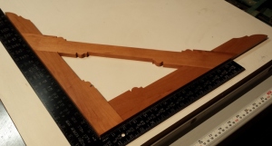
 The finish was fairly simple. I wiped on a coat of boiled linseed oil, and let it set for a week. On a very sunny day, I set the square out in the sun to let the cherry darken a bit. Once the oil had cured, I buffed it out using the Beall buffing system.
This turned out to be a very fun project for me, as well as a good challenge. I accomplished making some joinery that I have never done before, as well as pushed my hand tool skills further along.
 Wow! This turned out to be the biggest and most complex project I have completed yet in my wood shop. And I would do it again in a heart beat! I looked back on my first post for the router table, where I had defined the goals I wanted to achieve for the new table. I am happy to say I have achieved them all! The router table truly is a joy to use!
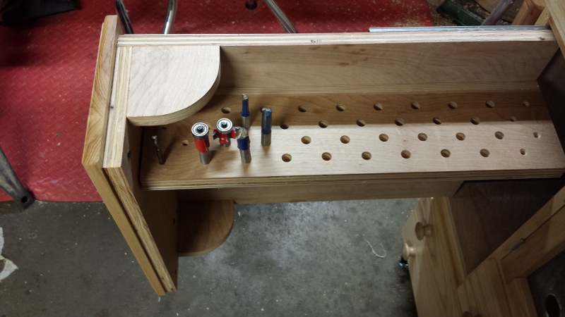
 he fence from the old table was another area of the router table that had some room for improvement. Overall the new fence is mostly a bigger version of the old one, with a sliding split front that I can have an opening that is sized to the bit being used, with a length of t-track for attaching feather boards, stops, and a guard. The big improvements I made are how the fence attaches and clamps down to the table, and the dust collection. On the old table I routed a couple grooves that a couple of carriage bolts would travel in. Those bolts went through a couple of holes the base of the fence with a couple of wing nuts to lock it in place. This worked fine, but what I didn’t like about it is that I had to completely disassemble them to remove the fence from the table.
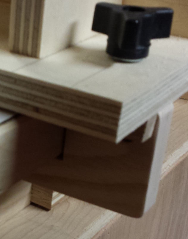
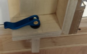 The first iterations when I loosened the knob, the clamp blocks remained engaged. Once I finally got the clamps working as needed I switched out the knobs with cam levers from Rockler, which work very well to quickly lock and unlock the fence.
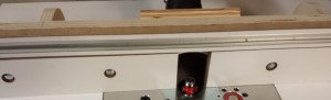
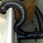 One of the top priorities for a new router table was dust collection. The router table has always been a big source of shavings and dust. The dust collection for the router table is done in two parts, divided between the space under the router table that contains the router and lift, and the fence. To accomplish this, I got a 4″ Y fitting where one of the forks is reduced to 2.5″. Using a scrap piece of hardwood, I marked the perimeter of the Y, that I then cut out the hole using the band saw and the oscillating spindle sander to get a good fit. Since I kept the back of the router table removable, I marked approximately where I wanted the DC to go in, and took off the back. I then used the piece I just made to mark precisely where the dust collection would go in. I cut out the opening with a jig saw. From there I double side taped the reference piece to the back, and used a flush trim bit on the router to get the opening properly sized and shaped. On the inside portion I ran a chamfer around the perimeter of the hole as well, which should help the flow a bit. While the back was off, I decided I didn’t want to glue the fitting to the back directly so that I could make tweaks as needed, so I lined up the scrap piece I had made to the hole and screwed it in place where I then glued the Y to it with Gorilla Glue. The foaming did very well to close up any gaps.
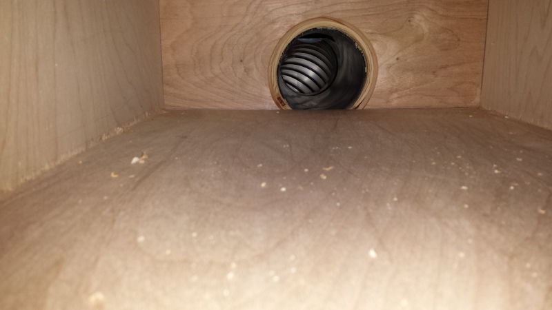
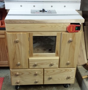
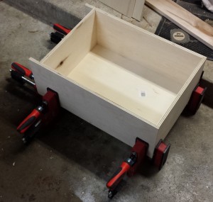 One of my requirements for a new router table was a cabinet that had plenty of storage. So I designed it with 4 traditional drawers and 2 vertical drawers. The traditional drawers are basic plywood boxes, with an applied hardwood front. The boxes were assembled using rabbets and dados. There is a groove in the bottom to accept a 1/4″ thick piece of plywood for the bottom. The drawer boxes are sized so that they slide in and out of the cabinet easily. The backs of the drawers are inset a couple inches so that they can slide out enough that I am able to get full access to the drawer contents, but it won’t fall out of the cabinet.
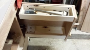 The vertical drawers are something unique I came up with, that will hopefully give me a greater amount of flexibility on my storage needs. The concept is very similar to what I did for the hand tool cabinet. The main panel is a 3/4″ thick piece of plywood attached to the sides of the cabinet with full extension drawer slides. A front is attached with brackets and pocket screws. The right vertical drawer I have a couple shallow boxes attached to it that stores everything I need for bit changes and adjustment. This has proven to be very useful. Currently the left vertical drawer is empty, but I plan to use this mainly for bit storage.
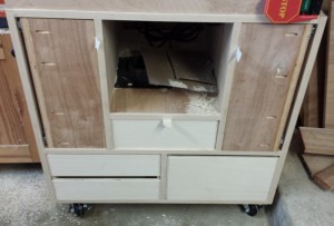 The fronts of the drawers are made from ash. The fronts for the bottom 3 drawers were made from one panel of wood so that I can get a good grain match. I also attempted to make the 2 smaller drawers look like they are one piece, though it is two. Attaching the drawer fronts turned out to be straight forward. Since I am turning the pulls on the lathe, I figured I could use that to my advantage. I measured out and predrilled screw holes with a fairly deep counter sink. I then put screws in enough that I could push them against the draw box. Once I was satisfied with the alignment I screwed the screws home. I then put it four more screws from behind to get a solid fit. For the space directly under the router table, the front was a piece of plywood which looked out of place next to all the ash. So I made a false front in the same style of the drawers.
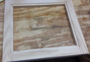 The door is similar to a frame and panel door, except that instead of a wood panel, it is using a plexiglass insert. I didn’t want to run a groove all the way around, so I used the router tablento put mortise on each end of the 2 stiles. I did this on the router table with a 1/4″ bit. Using a rabbet bit I made the tenons on the rails. I then glued up the frame. Using the same rabbet bit, I put a rabbet all the way around the back of the inside portion of the frame which is deep enough to accept the plexiglass and push pins to hold it in place. After routing out the rabbet, I used a couple chisels to square the corners. On the front, again inside the frame, I routed a round over. Using my rasp and some sand paper I cleaned up the corners. The plexiglass panel has holes drilled into it for back flow for the dust collection.
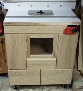 All that is left is the pulls. They aren’t done yet, and will likely be the last thing I do for the router table. If I don’t get them done before the final post on the router table, I will post a picture of them in a future general update post. Otherwise, from the front the router table looks complete visually. However, there is still a bit more to go on the build, which I will go over in the next post.